The outer heath is of PVC compound confirming to the requiremnets of type 6 compund of IS:5831-1970.
The colour of outer sheath is genereally Black.
CABLE CODE:
The following code is used for easy identification of the cables.
META PLAST 1.1KV SINGLE CORE, ALUMINIUM CONDUCTOR, PVC INSULATED
UNARMOURED & PVC SHEATHED CABLES AS PER IS:1554 (PART I) AMENDED UPTO DATE
Nominal cross sectional area |
Nominal thickness of Insualtion |
Nominal thickness of Outer Sheath |
Approx overall diameter |
Approx weight of cable |
Max. Dc conductor resistance at 200 C |
CURRENT RATINGS |
Direct in Ground |
In Duct |
In Air |
2 cables Amps |
3 cables Amps |
2 cables Amps |
3 cables Amps |
2 cables Amps |
3 cables Amps |
Sq.mm |
mm |
mm |
mm |
kg / km |
Ohm / km |
1 x 1.5 |
1.1 |
1.8 |
7.4 |
63 |
19.7 |
21 |
17 |
19 |
17 |
18 |
15 |
1 x 2.5* |
1.2 |
1.8 |
8.0 |
74 |
11.8 |
28 |
24 |
25 |
24 |
25 |
21 |
1 x 4* |
1.3 |
1.8 |
8.7 |
88 |
7.39 |
36 |
31 |
33 |
30 |
32 |
27 |
1 x 6* |
1.3 |
1.8 |
9.2 |
101 |
4.91 |
44 |
39 |
42 |
37 |
41 |
35 |
1 x 10* |
1.3 |
1.8 |
10.0 |
122 |
2.94 |
54 |
51 |
56 |
51 |
56 |
47 |
1 x 16 |
1.3 |
1.8 |
11.5 |
161 |
1.87 |
75 |
66 |
71 |
65 |
72 |
64 |
1 x 25 |
1.5 |
1.8 |
12.9 |
209 |
1.18 |
97 |
86 |
93 |
84 |
99 |
84 |
1 x 35 |
1.5 |
1.8 |
14.0 |
251 |
0.851 |
120 |
100 |
110 |
100 |
120 |
105 |
1 x 50 |
1.5 |
1.8 |
15.2 |
301 |
0.628 |
145 |
120 |
130 |
115 |
150 |
130 |
1 x 70 |
1.5 |
1.8 |
17.0 |
386 |
0.435 |
170 |
140 |
155 |
135 |
185 |
155 |
1 x 95 |
1.6 |
2.0 |
19.4 |
510 |
0.313 |
205 |
175 |
180 |
155 |
215 |
190 |
1 x 120 |
1.6 |
2.0 |
20.9 |
601 |
0.248 |
230 |
195 |
200 |
170 |
240 |
220 |
1 x 150 |
1.8 |
2.0 |
22.8 |
722 |
0.202 |
265 |
220 |
220 |
190 |
270 |
250 |
1 x 185 |
2.0 |
2.0 |
25.0 |
871 |
0.161 |
300 |
240 |
240 |
210 |
305 |
290 |
1 x 240 |
2.2 |
2.0 |
27.9 |
1098 |
0.122 |
335 |
270 |
270 |
225 |
350 |
335 |
* If required, cables can be made with stranded conductor also. *Not covered in IS : 1554 (Part 1) 1976
META PLAST 1.1 KV TWIN CORE, ALUMINIUM CONDUCTOR, PVC INSULATED INNER SHEATHED
UNARMOURED & PVC SHEATHED CABLES AS PER IS: 1554 (PART I) AMENDED UPTO DATE
Nominal cross sectional area |
Nominal thickness of Insualtion |
Minium thickness of Inner Sheath |
Normal thickness Outer Sheath |
Approx overallt of cable |
Approx weight of cable |
Max. Dc conductor resistance at 200 C |
CURRENT RATINGS |
Direct in Ground |
In Duct |
In Air |
Amps |
Amps |
Amps |
Sq.mm |
Mm |
Mm |
Mm |
Mm |
kg / km |
Ohm / km |
2 x 1.5 |
0.8 |
0.3 |
1.8 |
10.4 |
135 |
20.0 |
18 |
16 |
16 |
2 x 2.5* |
0.9 |
0.3 |
1.8 |
11.6 |
194 |
12.0 |
25 |
21 |
21 |
2 x 4* |
1.0 |
0.3 |
1.8 |
13.0 |
247 |
7.54 |
32 |
27 |
27 |
2 x 6* |
1.0 |
0.3 |
1.8 |
14.0 |
258 |
5.01 |
40 |
34 |
35 |
2 x 10* |
1.0 |
0.3 |
1.8 |
15.6 |
351 |
3.00 |
55 |
45 |
47 |
2 x 16 |
1.0 |
0.3 |
1.8 |
16.5 |
364 |
1.91 |
70 |
58 |
59 |
2 x 25 |
1.2 |
0.3 |
2.0 |
19.4 |
480 |
1.20 |
90 |
76 |
78 |
2 x 35 |
1.2 |
0.3 |
2.0 |
21.0 |
600 |
0.868 |
110 |
92 |
99 |
2 x 50 |
1.4 |
0.3 |
2.0 |
23.7 |
750 |
0.641 |
135 |
115 |
125 |
2 x 70 |
1.4 |
0.3 |
2.0 |
26.3 |
900 |
0.443 |
160 |
140 |
150 |
* If required, cables can be made with stranded conductor also. *Not covered in IS : 1554 (Part 1) 1976
META PLAST 1.1 KV THREE CORE, ALUMINIUM CONDUCTOR, PVC INSULATED INNER SHEATHED UNARMOURED & PVC
SHEATHED CABLES AS PER IS:1554 (PART I) AMENDED UPTO DATE
| Nominal cross sectional area |
Nominal thickness of Insualtion |
Minium thickness of Inner Sheath |
Normal thickness Outer Sheath |
Approx overallt of cable |
Approx weight of cable |
Max. Dc conductor resistance at 200 C |
CURRENT RATINGS |
Direct in Ground |
In Duct |
In Air |
Amps |
Amps |
Amps |
Sq.mm |
Mm |
Mm |
Mm |
Mm |
kg / km |
Ohm / km |
3 x 1.5 |
0.8 |
0.3 |
1.8 |
10.9 |
160 |
20.0 |
16 |
14 |
13 |
3 x 2.5* |
0.9 |
0.3 |
1.8 |
12.2 |
221 |
12.0 |
21 |
18 |
18 |
3 x 4* |
1.0 |
0.3 |
1.8 |
13.7 |
242 |
7.54 |
28 |
23 |
23 |
3 x 6* |
1.0 |
0.3 |
1.8 |
14.8 |
320 |
5.01 |
35 |
30 |
30 |
3 x 10* |
1.0 |
0.3 |
1.8 |
16.5 |
366 |
3.00 |
46 |
39 |
40 |
3 x 16 |
1.0 |
0.3 |
1.8 |
17.8 |
436 |
1.91 |
60 |
50 |
51 |
3 x 25 |
1.2 |
0.3 |
2.0 |
21.2 |
630 |
1.20 |
76 |
63 |
70 |
3 x 35 |
1.2 |
0.3 |
2.0 |
23.1 |
706 |
0.868 |
92 |
77 |
86 |
3 x 50 |
1.4 |
0.3 |
2.0 |
26.1 |
903 |
0.641 |
110 |
95 |
105 |
3 x 70 |
1.4 |
0.3 |
2.2 |
29.7 |
1200 |
0.443 |
135 |
115 |
130 |
* If required, cables can be made with stranded conductor also. *Not covered in IS : 1554 (Part 1) 1976
META PLAST 1.1 KV 31/2 CORE, ALUMINIUM CONDUCTOR, PVC INSULATED INNER SHEATHED UNARMOURED & PVC SHEATHED
CABLES CONFORMING TO IS :1554 (PART I) AMENDED UPTO DATE
Nominal cross sectional area |
Nominal thickness of insulation |
Minimum thickness of inner sheath |
Minimum thickness of Outer sheath |
Approx overall diameter |
Approx weight of cable |
Max. DC conductor resistance at 20°C |
CURRENT RATINGS |
Sq.mm |
Neutral
Sq.mm |
Main mm |
Neutral
Smm |
Mm |
Mm |
Mm |
Kg/ Km |
Main Ohm / km |
Neutral Ohm / km |
Direct in Ground Amps |
In Ducts Amps |
In Air Amps |
31/2 x 35 |
16 |
1.2 |
1.0 |
0.3 |
2.0 |
23.9 |
702 |
1.20 |
1.91 |
76 |
63 |
70 |
31/2 x 25 |
16 |
1.2 |
1.0 |
0.3 |
2.0 |
26.2 |
800 |
0.868 |
1.91 |
92 |
77 |
86 |
31/2 x 50 |
25 |
1.4 |
1.2 |
0.3 |
2.2 |
29.5 |
1027 |
0.641 |
1.20 |
110 |
95 |
105 |
31/2 x 70 |
35 |
1.4 |
1.2 |
0.3 |
2.2 |
33.5 |
1550 |
0.443 |
0.868 |
135 |
115 |
130 |
META PLAST 1.1 KV FOUR CORE, ALUMINIUM CONDUCTOR, PVC INSULATED INNER SHEATHED UNARMOURED & PVC SHEATHED
CABLES AS PER IS :1554 (PART I) AMENDED UPTO DATE
Nominal cross sectional area |
Nominal thickness of Insualtion |
Minium thickness of Inner Sheath |
Normal thickness Outer Sheath |
Approx overallt of cable |
Approx weight of cable |
Max. Dc conductor resistance at 200 C |
CURRENT RATINGS |
Direct in Ground |
In Duct |
In Air |
Amps |
Amps |
Amps |
Sq.mm |
Mm |
Mm |
Mm |
Mm |
kg / km |
Ohm / km |
4 x 1.5 |
0.8 |
0.3 |
1.8 |
11.7 |
180 |
20.0 |
16 |
14 |
13 |
4 x 2.5* |
0.9 |
0.3 |
1.8 |
13.1 |
225 |
12.0 |
21 |
18 |
18 |
4 x 4* |
1.0 |
0.3 |
1.8 |
14.8 |
269 |
7.54 |
28 |
23 |
23 |
4 x 6* |
1.0 |
0.3 |
1.8 |
16.0 |
316 |
5.01 |
35 |
30 |
30 |
4 x 10* |
1.0 |
0.3 |
1.8 |
17.9 |
411 |
3.00 |
46 |
39 |
40 |
4 x 16 |
1.0 |
0.3 |
2.0 |
20.3 |
532 |
1.91 |
60 |
50 |
51 |
4 x 25 |
1.2 |
0.3 |
2.0 |
23.9 |
719 |
1.20 |
76 |
63 |
70 |
4 x 35 |
1.2 |
0.3 |
2.0 |
26.0 |
897 |
0.868 |
92 |
77 |
86 |
4 x 50 |
1.4 |
0.3 |
2.2 |
30.1 |
1189 |
0.641 |
110 |
95 |
105 |
4 x 70 |
1.4 |
0.4 |
2.2 |
33.9 |
1548 |
0.443 |
135 |
115 |
130 |
* If required, cables can be made with stranded conductor also. *Not covered in IS : 1554 (Part 1) 1976
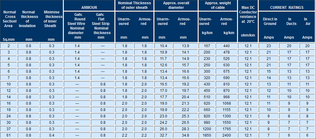
META PLAST 1.1KV TWIN CORE, ALUMINIUM CONDUCTOR, PVC INSULATED INNER SHEATHER ARMOURED & PVC SHEATHED
CABLES AS PER IS : 1554 (PART I) AMENDED UPTO DATE
Nominal cross sectional area |
Nominal thickness of Insulation |
Minimum thickness of Inner sheath |
ARMOUR |
Nominal thickness of Outer sheath |
Approx overall diameter |
Approx weight of cable |
Max Dc conductor resistance at 20°C |
CURRENT RATINGS |
|
Galv.Round Steel Wire Normal diameter |
Galv.Flat Steel Strip Normal thickness |
|
Direct in Ground |
In Ducts |
In Air |
Sq.mm |
mm |
mm |
mm |
mm |
mm |
mm |
Kg/km |
Ohm/km |
Amps |
Amps |
Amps |
2 x 1.5 |
0.8 |
0.3 |
1.4 |
-- |
1.8 |
13.6 |
410 |
20.0 |
18 |
16 |
16 |
2 x 2.5* |
0.9 |
0.3 |
1.4 |
-- |
1.8 |
14.8 |
472 |
12.0 |
25 |
21 |
21 |
2 x 4* |
1.0 |
0.3 |
1.4 |
-- |
1.8 |
16.2 |
568 |
7.54 |
32 |
27 |
27 |
2 x 6* |
1.0 |
0.3 |
1.4 |
-- |
1.8 |
17.2 |
632 |
5.01 |
40 |
34 |
35 |
2 x 10* |
1.0 |
0.3 |
1.4 |
-- |
1.8 |
18.3 |
750 |
3.00 |
55 |
45 |
47 |
2 x 16 |
1.0 |
0.3 |
-- |
0.8 |
2.0 |
19.7 |
770 |
1.91 |
70 |
58 |
59 |
2 x 25 |
1.2 |
0.3 |
-- |
0.8 |
2.0 |
21.2 |
800 |
1.20 |
90 |
76 |
78 |
2 x 35 |
1.2 |
0.3 |
-- |
0.8 |
2.0 |
22.9 |
920 |
0.868 |
110 |
92 |
99 |
2 x 50 |
1.4 |
0.3 |
-- |
0.8 |
2.0 |
25.6 |
1042 |
0.641 |
135 |
115 |
125 |
* If required, cables can be made with stranded conductor also. *Not covered in IS : 1554 (Part 1) 1976
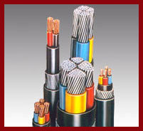
META PLAST 1.1KV THREE CORE, ALUMINIUM CONDUCTOR, PVC INSULATED INNER SHEATHER ARMOURED & PVC
SHEATHED CABLES AS PER IS : 1554 (PART I) AMENDED UPTO DATE
| Nominal cross sectional area |
Nominal thickness of Insulation |
Minimum thickness of Inner sheath |
ARMOUR |
Nominal thickness of Outer sheath |
Approx overall diameter |
Approx weight of cable |
Max Dc conductor resistance at 20°C |
CURRENT RATINGS |
Galv.Round Steel Wire Normal diameter |
Galv.Flat Steel Strip Normal thickness |
Direct in Ground |
In Ducts |
In Air |
Sq.mm |
mm |
mm |
mm |
mm |
mm |
mm |
Kg/km |
Ohm/km |
Amps |
Amps |
Amps |
3 x 1.5 |
0.8 |
0.3 |
1.4 |
-- |
1.8 |
14.1 |
440 |
20.0 |
16 |
14 |
13 |
3 x 2.5* |
0.9 |
0.3 |
1.4 |
-- |
1.8 |
15.4 |
520 |
12.0 |
21 |
18 |
18 |
3 x 4* |
1.0 |
0.3 |
1.4 |
-- |
1.8 |
16.9 |
613 |
7.54 |
28 |
23 |
23 |
3 x 6* |
1.0 |
0.3 |
1.4 |
-- |
1.8 |
18.0 |
680 |
5.01 |
35 |
30 |
30 |
3 x 10* |
1.0 |
0.3 |
-- |
0.8 |
2.0 |
19.4 |
720 |
3.00 |
46 |
39 |
40 |
3 x 16 |
1.0 |
0.3 |
-- |
0.8 |
2.0 |
20.1 |
766 |
1.91 |
60 |
50 |
51 |
3 x 25 |
1.2 |
0.3 |
-- |
0.8 |
2.0 |
23.1 |
920 |
1.20 |
76 |
63 |
70 |
3 x 35 |
1.2 |
0.3 |
-- |
0.8 |
2.0 |
25.0 |
1047 |
0.868 |
92 |
77 |
86 |
3 x 50 |
1.4 |
0.3 |
-- |
0.8 |
2.0 |
28.0 |
1249 |
0.641 |
110 |
95 |
105 |
* If required, cables can be made with stranded conductor also. *Not covered in IS : 1554 (Part 1) 1976
META PLAST 1.1KV 31/2 CORE, ALUMINIUM CONDUCTOR, PVC INSULATED INNER SHEATHER ARMOURED & PVC
SHEATHED CABLES AS PER IS : 1554 (PART I) AMENDED UPTO DATE
Nominal cross sectional area |
Nominal thickness of Insulation |
Minimum thickness of Inner sheath |
ARMOUR |
Nominal thickness of Outer sheath |
Approx diameter |
Approx weight of cable |
Max Dc conductor resistance at 20°C |
CURRENT RATINGS |
|
Galv.Flat Steel Strip |
|
Direct in Ground |
In Ducts |
In Air |
|
Main Sq.mm |
Neutral Sq.mm |
Main Sq.mm |
Neutral Sq.mm |
Mm |
Mm |
Mm |
Mm |
Kg/km |
Main
Ohm/km |
Neutral
Ohm/km |
Amps |
Amps |
Amps |
31/2 x 25 |
16 |
1.2 |
1.0 |
0.3 |
0.8 |
2.0 |
25.8 |
1048 |
1.20 |
1.91 |
76 |
63 |
70 |
31/2 x 35 |
16 |
1.2 |
1.0 |
0.3 |
0.8 |
2.0 |
28.1 |
1221 |
0.868 |
1.91 |
92 |
77 |
86 |
31/2 x 50 |
25 |
1.4 |
1.2 |
0.3 |
0.8 |
2.2 |
31.4 |
1529 |
0.641 |
1.20 |
100 |
95 |
105 |
METAPLAST 1.1 KV FOUR CORE, ALUMINIUM CONDUCTOR, PVC INSULATED INNER SHEATHED ARMOURED PVC
SHEATHED CABLES AS PER IS :1554 (PART 1) AMENDED UPTO DATE
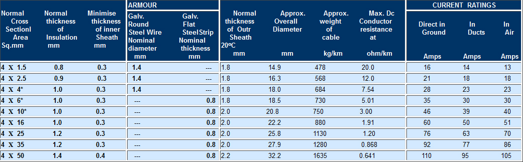
* If required, cables can be made with stranded conductor also. *Not covered in IS : 1554 (Part 1) 1976
METAPLAST 1.1 KV ANNEALED HIGH CONDUCTIVITY SOLID COPPER CONDUCTOR 1.5 Sq. mm. PVCINSULATED INNER SHEED, ARMOURED / UNARMOURED &
PVC SHEATHED CONTROL CABLES AS PER IS :1554 (PART 1) AMENDED UPTO DATE